As part of my Smart Home build, I need a proper network with segregated sub-networks for our computers, IoT & media devices, management and, of course, guests. The full network design and decision process will be the subject of another post, but I obviously need wi-fi - at least 3 different wi-fi networks in fact.
All the forum posts and information I can find say that the R9000 doesn't support VLANs in dd-wrt. I need VLAN support so that I don't have to have 3 or more different APs (one for each network SSID). Looking at the hardware spec (and the fact that the stock firmware supports limited VLANs), I figured that it should support VLANs, so I trawled the forums, looked at the code and learned about the toolsets included in dd-wrt and I made it work!
This post covers how I set up VLANs on my Netgear R9000 Nighthawk X10 in dd-wrt. I'm sure you will want a different setup (in fact this isn't my final setup either, but it shows the principle).
Pre-requisites
I am going to assume that you have installed dd-wrt with default settings on your Netgear R9000 Nighthawk X10 (there are plenty of guides on how to do this if you do a search and it is actually very easy) and that your other network equipment (switches and routers) are VLAN capable. Hopefully you know what network setup you want and roughly what VLANs and VAPs are if you've come to this page, but, just in case, here's a refresher:
- VLANs are Virtual Local Area Networks that allow you to logically separate your single physical, wired network into different sub-networks
- VAPs are Virtual Access Points and allow a single wi-fi AP to advertise multiple SSIDs (Service Set Identifiers or network names to most normal people).
In my setup I have a pfSense router/firewall, so I only want the R9000 to act as an AP. I also have a central DHCP server, so I won't be using the built-in DHCP service on dd-wrt (you can use this if you want, but don't forget to create new DHCP listeners for each VLAN later). Finally, I'm using the WAN port as my trunk port to my core switch. Feel free to alter the port assignments for your setup (I'll try to give you pointers when we get there).
Just to reiterate, this guide is for the Netgear R9000 and not any other router (although I am lead to believe that the XR700 is essentially the same router).
Initial config
A significant amount of the configuration can be done in the GUI, but the crucial part of getting VLANs to work has to be done at the command line and with startup scripts. I will perform as much config in the GUI as possible, as it makes it easier to understand and customise to your situation.
Let's dive in...
- Log in to your dd-wrt router and go to the Setup > Basic Setup tab

- To follow my guide and port assignments, set WAN Connection Type to disabled and check the box Assign WAN Port to Switch
- You will want to change the IP address onto the 192.168.15.x subnet if you want to implement the management VLAN that I use later, but it's not necessary.
- Also, if you have a separate DHCP server, disable the DHCP Server here
- Click the Save button at the bottom and then click on Apply Settings (wait a few minutes after this until the router has fully reloaded all components, which you can check by making sure the appropriate lights are on)

- Now go to the Setup > Advanced Routing tab
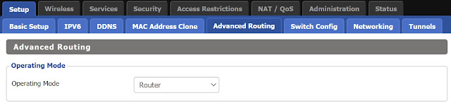
- Set Operating Mode to be Router, then Save and Apply Settings at the bottom
- Now go to the Wireless > Basic Settings tab to set up multiple SSIDs

- Make sure your wireless network is in AP mode and configure the wireless settings for your main network
- Next click on Add Virtual AP twice, so that you have 3 different networks, one physical and two virtual APs
- Fill in the SSIDs you want here (I use mainSSID-Guest and mainSSID-IoT), tick the Advanced Settings box and select AP Isolation for the guest network and Unbridged in Network Configuration for both VAPs (but not for the physical one)
- Do the same for the 2.4GHz radio as well, making sure that the SSIDs are the same as for the 5GHz radio so that your device can seamlessly switch between 2,4GHz and 5GHz depending on signal strength, etc.
- Click Save and then Apply Settings as before
- Now go to the Wireless > Wireless Security tab and enable WPA in the Security Mode field for all interfaces with a simple password for the Guest network and two different passphrases for the IoT and main networks. As you enable different options they will be saved, but any other changes you make will be discarded if you haven't explicitly saved them, so remember to click Save after each change and then click Apply Settings once after all the settings have been updated.
- Now go to the Setup > Switch Config tab. We're going to select some VLANs here so that they appear on the next tab we'll use.

- Don't try to reuse VLANs 1 & 2 as they have a special meaning in the switch (it may work, but I avoided using them). Similarly, VLANs 16-21 shouldn't be used. You could use higher numbers, but then they can't be configured in the GUI, so I use VLAN 4 for LAN traffic, VLAN 8 for guest access, VLAN 12 for IoT/Media devices and VLAN 15 for management. Set the ports as above. Note that I haven't changed the VLAN assignment of Port 5 deliberately.
- Click Save and then Apply Settings and let the router restart its services before carrying on (just check that both the wi-fi lights are back on)
- Once the router is ready, go to the Setup > Networking tab, where you should see entries for your VAPs and the VLANs you've just ticked.
- Now click the Add button under Create Bridge 3 times to create 3 new (4 in total) bridges.

- Name them br1, br2 and br3 (or whatever you want really) and make sure that STP is set to Off for all of them as above.
- Click Save and then Apply Settings so that these bridges are created.
- I tend to name all of the interfaces and bridges to make life easier for me when selecting the options later and I suggest that you do that now. You can change all of the names at once. The table below shows what I have called the built-in interfaces (the rest can be found in the following screenshot):
Interface Description eth0 SFP+ Port eth1 LAN Switch eth2 WAN Port wlan0 5GHz WLAN wlan1 2.4GHz WLAN - You also need to add an IP address (in the correct subnet) for each bridge. A simple addressing scheme would set br1 to 192.168.4.2 as it is VLAN 4 (don't forget that I am using pfSense as my router and therefore gateway, so I can't use 192.168.4.1 as that is my router. If this is going to be your router or you are using DHCP on dd-wrt then make this 192.168.4.1). Similarly, set br2 to 192.168.8.2 and br3 to 192.168.12.2 (note we didn't create a bridge for VLAN 15 as I don't need wireless for that).
- Click Save and then Apply Settings so that these bridges are updated.
- Now we can assign interfaces to the bridges

- Click the Add button 10 times to create 10 new assignments.
- Then add the assignments as in the diagram above, with the correct VLAN and 2 Wireless interfaces associated (please ignore the br0 eth1.15 above, you don't need that). For example, assign vlan4, wlan0 and wlan1 to br1. You will also need to assign vlan15 to br0 so that the base router IP is available on the management VLAN.
- Once again, click Save and Apply Settings to complete the initial configuration.


Unfortunately, the VLANS won't yet be working as the GUI can't actually assign the VLANs to the switch. This is because the R9000 actually has two switches inside it to expose 7 ethernet ports on the back of the device.
VLAN Config
This is where the magic happens, but it has to be done at the command line. By default, Telnet is enabled in the router, but I prefer to use SSH, which you can enable under the Services > Services tab by selecting Enable next to SSHd under Secure Shell (then click Save followed by Apply Settings). You can skip this step if you want.
The R9000 has two switches in it as mentioned above. In order for these two switches to talk to each other they each have 2 trunked ports connected to the other. I assume there are 2 so that you can split them between WAN and LAN ports (you can set any of the 7 ports to be WAN or LAN ports, so you could have 2 WAN and 5 LAN for example). I haven't tried splitting these trunk ports as I am using this as an AP, not an Internet gateway. Similarly, there are separate CPUs for the LAN (eth1) and WAN (eth2) interfaces. These are connected to 2 ports on the first switch and must be tagged to each VLAN we want to use. The switch ports are as follows:
sw port 0 -> Trunk to CPU(eth1)
sw port 5 -> Trunk to CPU(eth2)
sw port 4 -> Trunk to Switch1 sw port 0
sw port 6 -> Trunk to Switch1 sw port 5
sw port 3 -> WAN
sw port 2 -> LAN1
sw port 1 -> LAN2
# Switch1:
sw port 0 -> Trunk to Switch0 sw port 4
sw port 5 -> Trunk to Switch0 sw port 6
sw port 4 -> LAN3
sw port 3 -> LAN4
sw port 2 -> LAN5
sw port 1 -> LAN6
sw port 6 -> Not Used
In my experiments, I had lots of trouble getting the VLANs to work, so I did modify the NVRAM settings, even though the forums say that this is for a different chipset. I would still make the changes, as this works for me and sets up the GUI to match our VLAN assignments anyway.
Open Powershell (or a CMD prompt or other shell if you're not on Windows) and start up an SSH session (specify the logon account of root regardless of what username you set in the GUI and use your router's IP address):
ssh -l root 192.168.1.1
Now, the R9000 has vlan0 and vlan1 set in NVRAM, but vlan1 and vlan2 in the GUI. You can also see that port 5 is assigned to the CPU in NVRAM. This is clearly wrong for this switch, but I didn't update or alter this as my VLANs didn't work when I fiddled with it (this is why we didn't change the assignment of port 5 in the GUI). Type the following to check this:
nvram show | grep -i vlan.*ports | sort
You should see the following output:
Port 5 is the CPU port and port 0 is the WAN. Note that we have to include the CPU port in all the assignments. The next set of commands update the NVRAM settings to include our setup for the switch. Run each command in the SSH session (I will explain them below).
The first 4 lines assign ports to the 4 new VLANs we created. Taking vlan4ports as an example, 0t means tag port 0 with VLAN 4 as this will be our trunk port, then assign VLAN 4 to ports 1 & 2, plus include the CPU (port 5) so that it can process the packets.
The next 8 lines assign the VLANs to specific ports (yes, this is what the previous 4 lines should have done, but because of the issues around CPU ports it doesn't work yet). Port 0 is the WAN port and is being used to trunk all our VLANs, so they're all added here: 1&2 are the pre-existing ones; 4, 8, 12 & 15 are our new VLANs and VLAN 16 is a special tag to say that this is a trunked port (remember earlier I said that you can't use VLANs 16-21, this is why). Actually, we could add 18, 19 & 21 on the end here to force negotiation of Gb speeds, but these are added on automatically if we leave them off. Notice that we now use port 7 as the CPU port and trunk all VLANs to it.
The next 4 lines set the hardware name for these VLANs to be the same as for the 2 built in ones. The final line writes the updates to non-volatile ram so that is survives a reboot.
The VLANs still won't actually work yet, but this seems to be a prerequisite in my experimentation. The actual switch configuration happens in a tool called swconfig. If you type the following in the SSH session:
swconfig list
then you should get the following output:
This shows that you have the 2 switches that we talked about above. I suggest that you use either port 1 or 2 to do the configuration (as that one is already trunked to the CPU) and configure switch1 first, i.e. the opposite switch - don't cut off the branch you're sitting on!
The configuration for the 2 switches is as follows:
The router doesn't enable VLANs by default, it actually just splits the WAN port off by connecting it to a different CPU as far as I can see. So, we have to set enable_vlan to 1 (from 0). Remember the setup we're trying to achieve here: we're using the WAN port as a trunk to connect the AP to the rest of our network and then assigning the VLANs to specific LAN ports. In order for the VLANs to work across the two switches we must ensure that they are tagged onto the trunk ports as well (otherwise the packets will get dropped). A quick explanation of the configuration... line by line...
- Switch 0 VLAN 1: 0t = tag to LAN CPU, 4t & 6t = tag to Switch 1 trunks
- Switch 0 VLAN 2: 5t = tag to WAN CPU
- Switch 0 VLAN 4: 0t = tag to LAN CPU, 1 = assign to LAN 2, 2 = assign to LAN 1, 3t = tag to WAN port for trunking, 4t & 6t = tag to Switch 1 trunks
- Switch 0 VLANs 8, 12 & 15: 0t = tag to LAN CPU, 3t = tag to WAN port for trunking, 4t & 6t = tag to Switch 1 trunks
...and for switch1 (note we don't bother with the WAN VLAN on switch1)...
- Switch 1 VLAN 1: 0t & 5t = tag to Switch 0 trunks
- Switch 1 VLAN 4: 2 = assign to LAN 5, 0t & 5t = tag to Switch 0 trunks
- Switch 1 VLAN 8: 4 = assign to LAN 3, 0t & 5t = tag to Switch 0 trunks
- Switch 1 VLAN 12: 3 = assign to LAN 4, 0t & 5t = tag to Switch 0 trunks
- Switch 1 VLAN 15: 1 = assign to LAN 6, 0t & 5t = tag to Switch 0 trunks
When you apply the rules the system may become unresponsive for a few seconds while it does the reconfiguration. You may also need to swap your ethernet connection into port 6 to continue the configuration, assuming your AP is on a management VLAN IP address.
Test out the configuration with wireless and wired clients.
One final step is to add the swconfig code to the Startup script in the Administration > Commands tab. Paste the swconfig lines from above into the Commands text area and add a new line at the beginning with sleep 8 on it to delay the configuration until the system has booted up properly. Then click Save Startup and you're finally done!
Comments
Post a Comment